 |
Solar Panels (Photovoltaic Modules)
Solar Panels (Modules) are at the heart of any photovoltaic system, regardless if it is grid-tied, off-grid, or a hybrid system. In regards to a consumer solar installation, there are two main photovoltaic technologies used in solar panels across the variety of manufacturers. Specifically, Monocrystalline Silicon, and Polycrystalline Silicon. As far as a consumer is concerned, the major differences are efficiency and appearance.
So What is A Solar Panel? 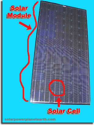
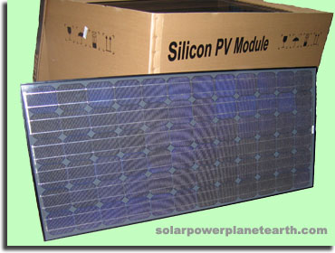
A solar panel is actually an array of individual solar cells, which are electrically interconnected and integrated into a weatherproof package. The picture to the right is of a standard monocrystalline solar module which allows you to clearly see the 4" silicon wafers (cells). For details on how a solar cell works, see our page on photovoltaics.
How are Solar Panels Characterized?
Standard parameters are used to characterize each solar panel for easy comparison between manufacturers. The following example data sheet is from a 224W Sharp Polycrystalline Solar Module, model ND-224U2.
| Cell Type | Polycrystalline Silicon |
|---|---|
| No. of Cells and Connections | 60 in series |
| Open Circuit Voltage (Voc) | 36.6V |
| Max. Power Voltage (Vpm) | 29.28V |
| Short Circuit Current (Isc) | 8.33A |
| Maximum Power Current (Ipm) | 7.66A |
| Rated Power (Pm)* | 224W (+10%/-5%) |
| Module Effeciency | 13.74% |
| Maximum System Voltage | 600V |
| Series Fuse Rating | 15A |
| Type of Output Terminal | MC Connector |
Cell Type
The type of technology used in each solar cell, either monocrystalline, polycrystalline, or thin film.
No. of Cells and Connections
This parameter tells you how many solar cells are contained within the solar panel, and referring to the example data sheet above, that they are all electrically connected in series. They are connected in series to minimize power loss due to resistive heating. To learn more about why this is the case, read our electricity 101 tutorial.
Open Circuit Voltage (Voc)
This is the voltage at the solar panel terminals when no load is applied. In other words the circuit is "open" and not connected to anything, and therefore not supplying any current.
Maximum Power Voltage (Vpm)
This is the voltage at the terminals of the solar panel when the maximum rated power is being drawn from it.
Short Circuit Current (Isc)
This is the amount of current that flows through the electrical leads when shorted, and is essentially the maximum amount of current that the solar panel can source.
Maximum Power Current (Ipm)
This is the current in Amperes that would flow through the terminals when the maximum rated power is being drawn from the solar panel.
Rated Power (Pm)
This is the maximum rated power. *This value is typically given under Standard Test Conditions (STC). See the description below on STC.
Module Efficiency
This value tells you how much of the solar energy that hits the panel is converted into electricity. In other words if the solar irradiance is 1000W/m^2, and the panel is a square meter, a 13.74% efficiency would give a solar panel output of 137.4W.
Maximum System Voltage
This is a parameter used to dictate how many solar panels can be put together in series, since voltages add when the sources are placed in series. Using the example data sheet above, since each solar panel has a Voc of 36.6V, if you were to put 10 of them in series, you would get a string voltage of 366V, which would be under the 600V limit. Most solar installations are setup in large series "strings" to minimize power loss in the wiring.
Series Fuse Rating
This parameter gives the appropriate fuse/breaker size for each "string" of series wired solar panels.
Type of Output Terminal
The output terminal describes the type of electrical connector installed on each of the two leads of the solar module.
*Standard Test Condition (STC)
This represents standardized test conditions that all solar panels are tested and rated at. STC is done at a temperature of 25C, a solar irradiance of 1000W/m^2, and an air mass of 1.5.
IV Curves 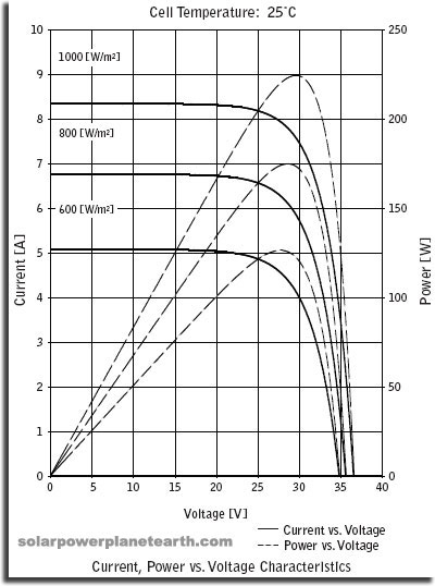
IV Curves are used to show the electrical performance of a solar panel. This allows the end user to determine where the "maximum power point" (MPP) of the particular solar panel is. Typically the MPP is automatically tracked (MPPT) by the inverter in a grid-tied system, or the charge controller in in off-grid system, and is not needed by the user.
IV stands for "Current vs. Voltage." In the plot to the right, which is also from the above mentioned Sharp 224W solar panel data sheet, you will notice two different types of curves, power vs. voltage and current vs. voltage. Each of these two different curves have three sub-curves for different amounts of solar irradiance, in watts per square meter.
You will notice that as the voltage increases, the current does not change very much until you approach the open circuit voltage at which time the current drops to zero as you would expect.
In regards to the power vs. voltage curve, you will notice that the highest point on the curve indicates the maximum power output. If you were to follow the highest point on this curve, and match it to the corresponding point on the current vs. voltage curve, you will obtain the maximum power voltage (Vpm) and maximum power current (Ipm), as specified in the table above.
For a better understanding of current, voltage, and power, visit our electricity 101 tutorial.